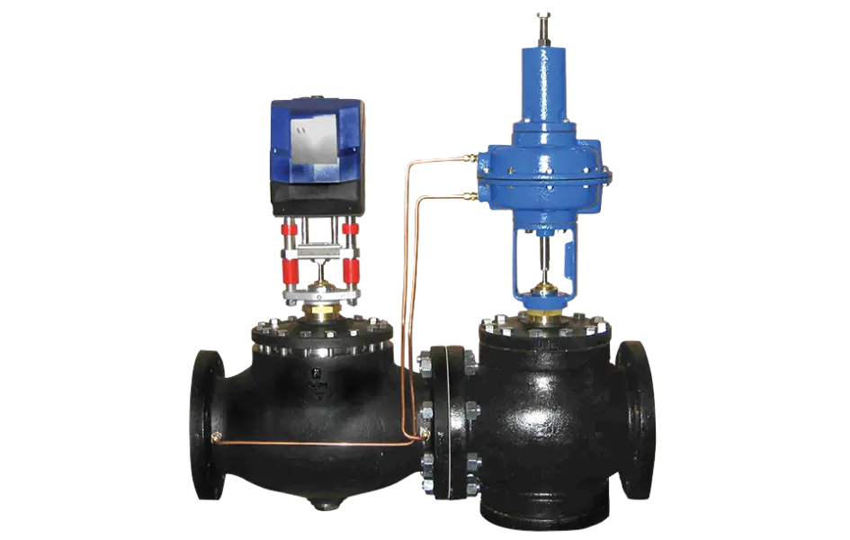
A PICV integrates a modulating control valve with a self-acting differential pressure regulator. The regulator maintains a set ΔP across the control valve, ensuring flow rate remains stable and unaffected by system pressure fluctuations.
2½ to 10 in. · DN65 to DN250
Cast iron · ANSI 125 / PN16 flanged
Water / water-glycol · 2 to 82 °C
Adjustable ΔP Regulator: 2 to 8 psi
How Does the Warren Controls PICV Operate?
With a conventional control valve, flow rates fluctuate at a given position whenever differential pressure changes. The Warren Controls PICV integrates two components in series: a control valve that modulates flow based on the control system signal, and a self-contained mechanical regulator that adjusts resistance to stabilize differential pressure across the valve. This engineered design ensures reliable, predictable control performance throughout all allowable operating conditions.
Two valves in series
The first unit modulates the flow to the thermal load, while the second compensates for system pressure variations. Both bodies are fully assembled and interconnected.
Self-Operated Differential Pressure (ΔP) Control
The differential pressure control valve is actuated by medium pressure, requiring no external control signal from the BMS.
Enhanced Control Stability
Differential pressure (ΔP) compensation mitigates uncontrolled flow fluctuations when pumps or parallel branches shift operating states.
Pre-calibrated assembly
Warren Controls specifies factory-assembled packages complete with sensing taps and impulse lines, pre-configured for differential pressure control according to project setpoints.
PICV: Type 23 or 22 Valve with Type 72 Controller
A PICV is a complete assembly: the electric control valve is either a Type 23 (2½" to 6") or a Type 22 (8" and 10"), consistently paired with a Type 72 self-operated differential pressure controller.
MODULATING VALVE · SMALL BORE
Type 23 · Control Valve
For 2½" to 6" PICV assemblies, the Type 23 modulating valve features a cylinder-balanced single seat and an electric actuator, delivering Class IV shut-off leakage integrity.
Diameters
2½ to 6"
Design and Construction
Balanced Single-Seat
Packing & Seals
Bronze or 300 series stainless steel
Seat leakage
Class IV
A single valve size can accommodate multiple reduced port configurations. Maximum flow rates and internal seals must be verified based on trim selection and process fluid.
MODULATING VALVE · LARGE SIZES
Type 22 · Control Valve
For 8- to 10-inch assemblies, the control valve is a Type 22 balanced double-seated design. Sizing charts indicate multiple port options, complete with stainless steel internal trim for these diameters.
Diameters
8 and 10 in.
Design and Construction
Double-Balanced Seat
Trim
300 Series Stainless Steel
Seat leakage
Class III
The double seat does not offer the same shut-off integrity as the Type 23. Tight shut-off requirements must be specified in the quote request.
ΔP CONTROL · SELF-OPERATED
Type 72 · Differential Pressure Regulator
The Type 72 differential pressure regulator pairs with the Type 23 or Type 22 modulating control valve. Its diaphragm automatically adjusts the differential pressure across the valve, requiring no additional control signal.
Function
Stabilize Differential Pressure (ΔP)
Spring Adjustment
2 to 8 psid*
Order
Self-operated, medium-controlled
Design and Construction
Type 72 · Double Seat
*Two spring ranges are specified based on the setpoint. Available loop pressure and maximum flow rate remain critical factors.
Water, Materials, Connections, and Operating Limits
General PICV data should not be extrapolated across all assemblies. The body, trim, actuator, and system operating conditions must be verified as a complete package.
BODY AND PROCESS MEDIA
Cast Iron and ANSI 125 / PN16 Flanges
The manufacturer's product data sheet specifies cast iron bodies with flat face (FF) ANSI Class 125 or PN16 flanged connections. Please verify the exact standard and bolt pattern drilling prior to any replacement.
Bronze, Stainless Steel, and Sealing Solutions
Internal components are available in bronze or 300 series stainless steel. Type 23 configurations specifically utilize EPDM seals with bronze trim or Fluoraz seals with stainless steel trim; please verify compatibility with your water treatment system.
Media Temperature
The specified operating range is 35 to 180°F (approximately 2 to 82°C) for water, chilled water, and compatible water-glycol mixtures. This is not a generic valve engineered for steam or thermal fluid applications.
LOOP SIZING
Differential pressure setpoint
The differential diaphragm controls an adjustable set point, supported by a low- or mid-range spring. The technical data sheet indicates approximately 2 to 8 psid, with factory pre-setting.
Available Flow Rates and Operating Pressures
Warren Controls charts correlate valve size, port size, ΔP setpoint, and maximum flow rate. The rated 50:1 rangeability relies on proper sizing matched to the operating load.
Layout and Orientation
The specified installation is for horizontal piping with actuators mounted vertically above the valves. Ensure adequate clearance for maintenance access and pressure-sensing lines.
To determine the proper configuration, please specify the minimum/normal/maximum flow rates, available ΔP, operating temperatures, fluid medium (water or water-glycol), flange specifications, supply voltage, and control signal type.
Where should you deploy a Warren Controls PICV?
Pressure-independent technology addresses water loops subject to dynamic operating hydraulic conditions. It does not, however, eliminate the need for proper flow calculation, head loss sizing, or water quality management.
VALVE AUTOMATION
Electric Actuator and Self-Operated Differential Pressure Regulator
The PICV serves two distinct functions: the control valve is equipped with an actuator and receives setpoints from the BAS/BMS, while the differential pressure regulator adjusts mechanically. Warren Controls specifies several electric actuators based on size, control signal, supply voltage, and fail-safe strategy.
24 V or line power, depending on model
Electrical configurations support various power supply options, notably 24 VAC/DC or 115/230 VAC depending on the actuator. Wiring connections must not be inferred solely from the PICV designation.
0/2–10 V or 0/4–20 mA
Analog control and position feedback options are available depending on the E029/E031 or ILEA part numbers. The BMS controller remains external to the assembly.
Fail-safe depending on configuration
Fail-in-place, fail-open, or fail-close functionality depends on the selected actuator package and accessories. Fail-safe operation must never be assumed.
How do you properly size and prepare for a PICV installation?
Accurate data minimizes the risk of selecting an assembly that is oversized, undersized, or unable to achieve its target ΔP.
HYDRAULICS
Nominal flow rate and minimum flow rate
Flow rates at minimum and maximum conditions, loop ΔP, and pressure drops across heat exchangers and accessories.
MEDIA
Temperature and Glycol
Treated water or water-glycol solution, with glycol concentration and operating temperature within the allowable range.
INSTALLATION
Flanges and Available Clearance
DN/NPS, flange standard, flow direction, horizontal orientation, and maintenance access.
AUTOMATION
Voltage, Signal, and Fail Position
BMS power supply, analogue signal, expected feedback, and fail-safe strategy upon power loss.
LES ATOUTS DE VAMECA
VAMECA assists you in gathering hydraulic and control data, determining the compatible configuration, and preparing the manufacturer inquiry. Availability, lead times, and compliance documentation are confirmed upon quotation.
FAQ
Pressure-independent, DN65 to DN250, water-glycol, ΔP setting, electric control, and installation.
Warren Controls PICVs: Selection and Quoting in Quebec
Whether for a chilled water system, heating loop, or heat exchanger, VAMECA delivers the technical expertise to help you select the ideal Warren Controls PICV tailored to your flow rates, pressures, end connections, and control specifications.
Flow Rate Analysis
Sizing based on system load, peak flow rate, and loop pressure fluctuations.
Project-Integrated Order
Verification of the actuator, power supply, signal, and required fail-safe position.
Technical dossier verified
Official data sheet, end connections, mounting orientation, documentation, and commercial terms for the selected part number.