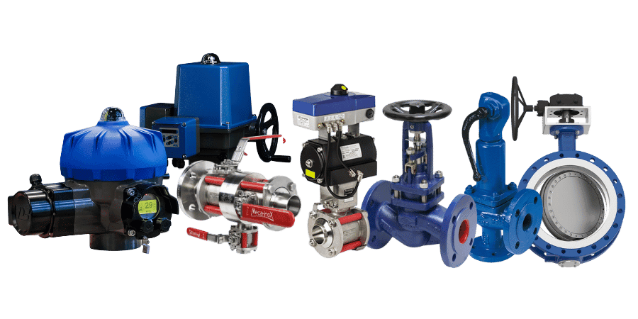

The 1840 is an unbalanced two-way valve. The 1843 features a balanced plug that reduces operating torque, particularly under high differential pressures. Its internal O-ring seal requires a sufficiently clean process media.
NPS ½ to 12 in. depending on the model
Class 125/250 Cast Iron Flanges · Class 150/300 Carbon/Stainless Steel Flanges
Cv up to 1,649 depending on configuration
2-Way and 3-Way · Pneumatic
A comprehensive line of globe valves engineered for industrial piping systems
The difference between the 1840 and 1843 series lies in the plug balancing and the thrust required from the pneumatic actuator. For three-way systems, the 1850 mixes two inlets, whereas the 1852 diverts one inlet to two outlets. Shut-off classes and pressure limits vary depending on the construction.
Flow Characteristics
Two-way: linear or equal percentage plugs. Three-way: linear plugs for mixing and diverting applications.
Materials of Construction
Cast iron, WCB cast steel, or CF8M stainless steel body; 316 stainless steel or Alloy 6 trim depending on the selected configuration.
Operating Range
50:1 turndown ratio across multiple configurations; the 1850 in sizes ½ to 2 in. delivers a 30:1 range. Cv is dependent on valve size and trim selection.
Stem Packings
PTFE, EPDM, or graphite packing solutions tailored to your media and temperature requirements. Extended bonnet configurations are available for specific high-temperature services.
The 1840, 1843, 1850, and 1852 configurations
Balanced or unbalanced two-way, mixing, and diverting: four distinct configurations, each featuring dedicated size ranges and sealing classes.

TWO-WAY CONTROL
1840 / 1843 · 2-Way
The 1840 utilizes an unbalanced plug, whereas the 1843 features a balanced plug design that reduces operating torque under high differential pressures. The 1843 is engineered specifically for relatively clean process media.
Diameter
6 to 12"
Body
Cast Iron · WCB · CF8M
Specification
Linear or Equal Percentage
Sealing Solutions
Standard Class IV
Two options: the 1840 for unbalanced control, or the 1843 when plug force requirements call for a balanced assembly.

3-WAY · MIXING
1850 · Mixing Valve
The 1850 typically blends two inlets into a single common outlet, delivering a linear flow characteristic. For sizes from ½ in. to 2 in., the manufacturer also permits reverse flow for select diverting applications.
Diameter
½ to 12"
Flow
2 inlets / 1 outlet
Internal Components
316 Stainless Steel · Linear
Rangeability
30:1 (½–2 in.) · 50:1 and above
Class IV shut-off. Mixing solution suitable when inlet pressures are compatible; for smaller line sizes, a flow-reversal bypass configuration can be evaluated.

3-WAY · DIVERTING
1852 · Diverter Valve
The 1852 typically diverts one inlet flow to two outlets with Class II seat leakage shutoff. Reverse flow for mixing applications is only permissible upon engineering review and approval by Warren Controls.
Diameter
2½ to 12"
Flow
1 Inlet / 2 Outlets
Sealing Solutions
Class II
Differential Pressure
50 psid max. between high/low ports
For diverting liquid service: verify piping configuration, port pressures, and the 50-psid differential limit. For reverse-flow mixing applications: consult the manufacturer.
Materials, Sealing, and Operating Conditions
Selecting the right part number involves more than just pipe size: the process fluid, differential pressure, leakage class, and thermal conditions all drive the proper specification.
MATERIALS AND SEALING SOLUTIONS
Bodies and Flanges
Cast iron with Class 125/250 flanges, or WCB carbon steel and CF8M stainless steel with Class 150/300 flanges, depending on available sizes.
Internal Packings and Seals
TFE V-Ring: suitable for steam and select chemicals, rated from 60 to 450°F depending on configuration. EPDM: designed for water service, but incompatible with oil-based fluids. For 1843 and 1852 series, verify O-ring compatibility when exposed to ketones and other solvents.
Graphite Packing and Extended Bonnet
Select configurations featuring graphite packing and an extended bonnet can withstand temperatures up to 800°F. Note that this process fluid temperature rating does not automatically apply to the actuator or accessories; their specific thermal operating limits must be verified.
ACTUATION AND CONTROL
Flow Characteristic
Linear or equal percentage depending on the two-way model; linear for three-way 1850 and 1852 models.
Differential Pressure
Monitor the ΔP during throttling and shut-off conditions. For model 1852, ensure the differential between the upper and lower ports does not exceed 50 psid.
Signalling and Safety
Pneumatic actuation or electro-pneumatic positioning: please specify the signal, air supply pressure, and required fail-safe position.
To validate your selection, please provide the upstream and downstream pressures, minimum/normal/maximum flow rates, operating temperature, process fluid, and control signal specifications.
Which piping systems and networks are suitable for the Warren Controls Series 1800?
The 1840/1843 series are specified for liquid, gas, and steam service, while the 1850/1852 three-way configurations are engineered for liquids. Materials of construction and packing must be verified based on your specific process conditions.
ACTUATION AND ACCESSORIES
Pneumatic Actuators and Positioners
The Warren Controls specification sheet pairs DL84/DL115 diaphragm actuators and cylinder actuators with various body sizes. Actuator selection is driven by thrust calculations and fail-safe mode requirements.
DL84 and DL115 Diaphragms
Diaphragm actuators available with various spring ranges. Pneumatic cylinders are also offered based on valve size and required thrust.
3–15 psi and 4–20 mA signals
Direct pneumatic control or electropneumatic positioner, featuring standard or split-range signal options to match your installed instrumentation.
Valve Positioners and Feedback Systems
VAC V200 positioners and 4–20 mA feedback or limit switch options are included in the documented configurations.
Required Specifications for a Series 1800 Valve
The nameplate from an existing valve, a piping schematic, and operating parameters streamline the validation of a drop-in replacement.
REPLACEMENT
Nameplate
A photo of the nameplate, along with the part number and serial number, ensures accurate identification of the configuration to be replaced.
CONNECTIONS
Flanges and Face-to-Face Dimensions
Please specify the diameter, flange class, and available face-to-face dimensions to verify the sizing of the proposed valve body.
PROCESS DATA
Flow Rates and Differential Pressure
Please provide the minimum, normal, and maximum flow rates, as well as the upstream and downstream pressures, to verify the Cv and required actuation torque.
ORDER
Signal and Fail-Safe Position
Specify the 3–15 psi or 4–20 mA signal, available instrument air supply, and required fail-safe position.
LES ATOUTS DE VAMECA
Whether for a new installation or a retrofit, VAMECA helps you gather the right technical data, evaluate Warren Controls configurations, and prepare your RFQ—without relying on assumptions about stock levels or lead times.
FAQ
2-way and 3-way configurations, pneumatic actuation, Cv values, compatibility, and drop-in replacement.
Your Canadian Technical Contact for the Warren Controls 1800 Series
VAMECA supports control and regulation projects from process data analysis through to product selection and manufacturer consultation.
Local Technical Support in Quebec
A dedicated local contact for quotation requests, piping connection specifications, and on-site installation constraints.
Operating Conditions Analysis
Pressure, flow rates, temperature, media, and actuation requirements are thoroughly evaluated prior to recommending a Series 1800 configuration.
Manufacturer Verification
We approve options 1840, 1843, 1850, and 1852, as well as the applicable documentation for the proposed reference.