In an industrial network, not all valves perform the same function. Some isolate — they open or close fully. Others regulate — they continuously modulate a fluid’s flow, pressure, or temperature. This distinction fully determines the selection of the equipment, actuator, and control system.
1. Isolation vs regulation: two different operating logics
An isolation valve (on/off) has only two positions: open or closed. It isolates a section of the network, protects equipment, or enables maintenance intervention. Its design is optimized for tight shutoff in the closed position and low pressure drop in the open position.
A control valve operates in intermediate positions, continuously and with precision. It receives a control signal (4–20 mA, 0–10 V, digital signal) and positions its plug at a specific angle or lift to maintain a setpoint — flow, pressure, temperature, or level. Its design is optimized for linearity, repeatability, and service life under modulation conditions.
⚠ Common mistake: using a standard isolation valve in an intermediate position to "regulate" flow. This causes rapid seat wear, cavitation, and complete loss of tight shutoff within a few weeks. A control valve is designed to operate at all positions — an on/off valve is not.
2. The three main families of control valves
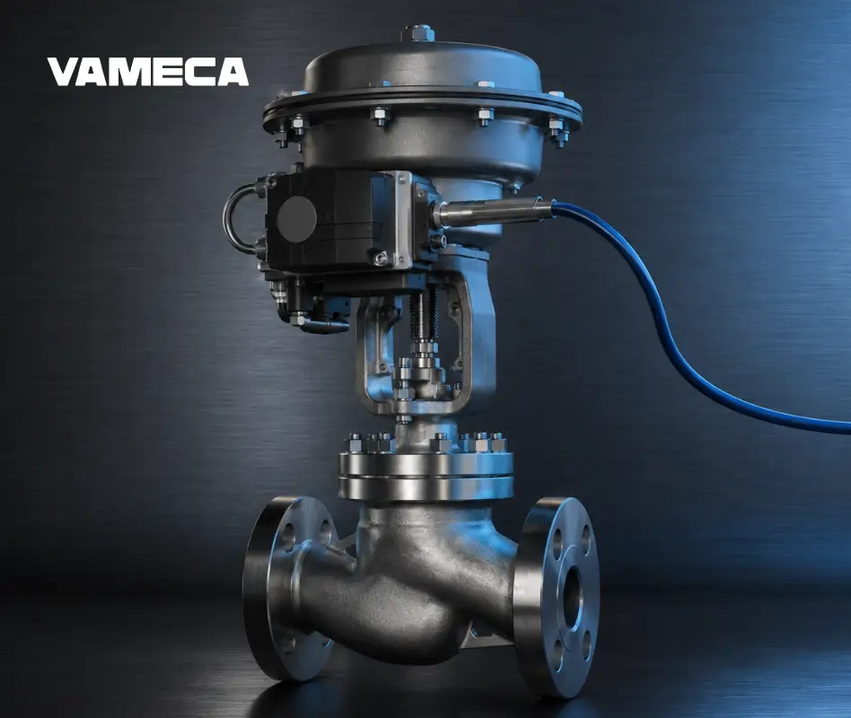
The globe valve
The globe valve is the historical benchmark in industrial control. Its plug moves vertically onto a horizontal seat, enabling very fine flow control even at low openings. It is particularly well suited to high-pressure fluids, steam, and applications where control accuracy is critical.
Strengths: excellent accuracy, good resistance to cavitation, wide range of available Kv values
Limitations: high pressure drop in the open position, large footprint, high operating torque on large diameters
Typical applications: steam, hot water, chemical processing, pharmaceutical
Butterfly valve with positioner
For large diameters (DN 100 and above), the butterfly valve equipped with an electro-pneumatic positioner offers a compact and cost-effective control solution. Its regulating characteristic is less linear than that of a globe valve, but more than sufficient for flow control in water, heating, or less demanding process applications.
Strengths: low cost for large diameters, lightweight, easy to automate
Limitations: imprecise control below 15° opening, less suitable for slurries
Typical applications: water treatment, HVAC, cooling circuits, district heating
The ball valve with positioner
The ball valve can be adapted for control service by adding an intelligent positioner and a suitable actuator. This configuration is common in standard industrial processes where a single technology is preferred for both isolation and regulation.
Strengths: versatile, widely available, cost-controlled, easy to maintain
Limitations: less precise regulating characteristic than a globe valve, seat wear under intensive continuous modulation
Typical applications: gas, compressed air, standard liquid processes, utilities
3. The Kv coefficient: the key sizing parameter
The Kv is the central parameter in selecting a control valve. It expresses the valve’s capacity to pass fluid: it is the flow rate of water at 15°C, in m³/h, passing through the fully open valve under a 1 bar pressure drop.
The higher the Kv, the more hydraulically "open" the valve is. An oversized valve (Kv too high) will operate continuously at very low opening — an unstable zone, with rapid wear. An undersized valve (Kv too low) will create excessive pressure drop and limit production.
✅ Sizing rule: in control service, the valve should operate between 20% and 80% of its maximum opening under normal service conditions. This leaves margin for minimum and maximum flows without entering unstable zones.
Simplified calculation of required Kv
For a liquid (water or equivalent fluid):
Kv = Q × √(ρ / ΔP)
Q = flow rate in m³/h
ρ = relative fluid density (1 for water)
ΔP = available pressure drop across the valve in bar
For steam and gases, the calculation is more complex (compressibility, critical flow) and requires manufacturer-specific sizing tools or assistance from a specialist.
4. Regulating characteristics
The regulating characteristic describes the relationship between plug position (% open) and the flow passing through the valve. Three main characteristics exist:
Characteristic | Behaviour | When to use it |
|---|---|---|
Linear | Flow increases in proportion to opening. 50% open = 50% of max Kv. | Processes with constant differential pressure, incompressible liquids |
Equal percentage | Each additional % of opening increases flow by a constant percentage. Exponential curve. | The most common in industry — adapts to differential pressure variations |
Quick opening | Maximum flow is reached within the first few % of opening. Concave curve. | Fast on/off valves, safety applications, blowdown |
In practice, the "equal percentage" characteristic is used most often because it naturally compensates for differential pressure variations in the network — which is the case in nearly all real industrial installations.
5. The actuator and positioner: the brain of control
A control valve without a positioner is like a car without a steering wheel. The positioner receives the control signal (from the PID controller or SCADA system) and precisely positions the plug by comparing the demanded position with the actual position.
Electro-pneumatic positioner
It converts an electrical signal (4–20 mA) into air pressure to operate a pneumatic actuator. This is the most common configuration in process industries: robust, precise, and suited to harsh environments.
Smart positioner
Modern positioners integrate advanced functions: valve condition diagnostics, wear detection, digital communication (HART, Profibus, Foundation Fieldbus). They integrate into Valve Automation 4.0 architectures for predictive maintenance.
Electric actuator with integrated positioner
For applications where compressed air is not available, modern electric actuators integrate the positioner directly. They offer native digital connectivity and high positioning accuracy, at the cost of slower actuation.
6. Typical applications by industrial sector in Canada
Sector | Application | Recommended valve type |
|---|---|---|
Process steam | Pressure regulation, temperature control | Globe valve + pneumatic actuator |
Water treatment | Flow control on large pipelines | Butterfly valve + electric positioner |
Food and beverage | Precise dosing, concentration control | Stainless steel globe valve + HART positioner |
Petrochemical | High-pressure control, corrosive fluids | Alloy globe valve + HazLoc-certified positioner |
Industrial HVAC | Balancing, heating control | Ball valve or butterfly valve + electric actuator |
Pharmaceutical | Sterile dosing, clean steam | Polished stainless steel globe valve + smart positioner |
7. Key selection considerations
Cavitation and flash
When a valve creates a significant pressure drop across a liquid, the pressure can fall below the fluid’s vapour pressure and cause bubble formation — this is cavitation. The implosion of these bubbles generates vibration, noise, and rapidly erodes the seats. Globe valves and certain ball valves have specific anti-cavitation plug profiles.
Aerodynamic noise
In high-velocity gas or steam control, valves can generate significant noise levels (up to 110 dB). Models with anti-noise cages or pressure reducers in series help keep installations within regulatory limits.
In summary
Choosing a control valve means answering four fundamental questions:
What fluid? — Nature, temperature, pressure, presence of particles, or corrosion
What Kv is required? — Nominal flow and min/max flow, available pressure drop
What control accuracy is needed? — Modulation range, required stability, response time
What integration is needed with the control system? — 4–20 mA signal, HART, Modbus, SCADA/DCS
At VAMECA, every control project is analysed against these criteria to propose the most suitable valve-actuator-positioner assembly, compliant with applicable Canadian standards.


